Shaft Installation - Part I
Once the internal framing was installed, I began the process of installing the propeller shafts. Before I get into details, I'll take a moment to describe
the shaft assemblies themselves.
Use the (vertical) scrollbar at right as needed. Clicking on any thumbnail will take you to a larger version of the photo.
Shaft Hardware
There is woefully little primary documentation on the web regarding the shafts, propellers, or shaft housings. It is possible to purchase plans from various
outlets, but these plans are drawings created by the seller, with no citation as to the source, or where the dimensions came from. I believe there exist such documents,
but they are either buried in some government archive (perhaps next to the Ark of the Covenant?), or the person(s) in their possession doesn't feel like sharing them.
So it is very difficult to arrive at precise dimensions - usually measuring a photograph (always dangerous) or tracing a dimensionless drawing.
At any rate, it seems the propeller shafts themselves are 24-inches in diameter while the stuffing boxes and strut tubes are somewhere between 44- and 48-inches. To create
this geometry I used 0.25" 304-stainless for the shafts, 0.50" brass for the stuffing boxes and strut tubes, and 9/32" brass tube for the bushings. I purchased the propellers
from Keith Bender, a machinist by profession who fabricates exquisite scale propellers to order. I specified 1/2-inch hubs, and to maintain fidelity to the prototype I went
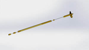
with threaded parts (rather than set-screw type retainers). I modeled both shaft configurations (inboard and outboard) in Solidworks to
determine basic lengths. The image below shows the outboard shaft.
A Word About the Propellers
At this point I'd like to take a moment to make a few comnments regarding my experience with Keith Bender. I've never met Keith in person, but have purchased several sets of his
props in different scales and for different ship models. In my line of work I have run into many companies and independent vendors who provide custom products. Many of these
are very proficient at what they do: some are what I would categorize as true artisans. Keith is in this latter group: one look at his work and you realize he has not only
skill, but a real love for what he does. Each propeller is a work of art, and at what I consider a reasonable price. If you have need of gorgeous scale propellers, please
do not hesitate to contact him (click here to email Keith)!
Shaft Placement
The next issue to be resolved is the placement of the shafts within the hull. Some of this puzzle is completed for you - the inboard shafts must sit just outboard of the
INBOARD face of the tunnel. In addition, the height of the inboard shafts' exit from the tunnel is established by the shape of the aft end of the tunnel. Fortunately, there
do exist some detailed drawings of various frames within the hull which provide fairly precise dimensions as to shaft angle and position: unfortunately, on my hull the port/starboard
tunnel walls are too close together by about 1/2-inch. This leaves you with the option of placing the shafts a) relative to the tunnels, or b) at the correct spacing. I
opted for former as I think the dimensional error will be less noticeable.
Note that the traditional method appears to use 3/16-inch shafts and correspondingly-smaller stuffing boxes. I originally purchased material - and propellers - in this size
BEFORE I did all my homework (duh...). So I have parts for each size - the larger size, despite being only 1/16" larger in diameter, is satisfyingly more massive and - in my
opinion - looks much more at home on this huge hull.
Once I had all the hardware together, Solidworks once again was put to work to model the shafts in the hull. I placed the models of the shafts into the model of the hull
per the dimensions I had generated after considerable effort. Once in place I was able to create patterns for jigs to locate the fore and aft ends of the shafts in the physical hull,
as well as locate the correct position for the outboard shafts' exit points.
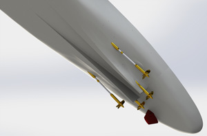
Note that altough the (incomplete) documents I have show a longitudinal angle with respect to the keel of ~ 1.8-degrees, I was strongly urged to keep this angle at around
one degree. So I did. Another interesting item to note is that the outboard shafts - in addition to the longitudinal offset - have a lateral angle with respect to the center
plane of ~ 2.25-degrees. The image below shows the final position of the shafts within the 3D model.
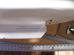 |
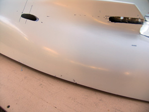
The first step was to mark the location of the inboard shaft exit on the tunnel. I used a 1-degree entry angle, and centered the shaft vertically
on the hull's profile as shown in the photo. |
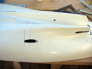 |
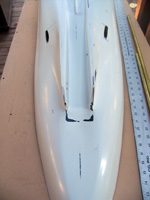
Next I marked the location of the outboard shaft, then cut the hull as shown. I used a 32mm saw/mandrel in my moto tool, in addtion to standard
cutting bits. I *HATE* fiberglass, and so used surgical gloves and a large fan on hi to keep the debris off my skin. |
| |
|
|
|
 |
Another view of the hull cutouts. Note that I did penetrate the inner wall of the tunnel - the was unavoidable in my effort to get the shaft as
close as possible to the inner surface. Once I glass the shaft into place, a little bondo will make short work of this damage. |
 |
Looking forward at both sides' cutouts. |
| |
|
|
|
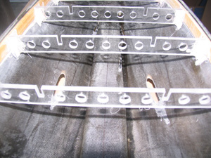 |
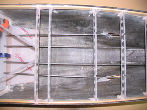
Here's how it looks from the inside. Note the areas forward of the exit points which have been thinned down to clear the stuffing boxes. |
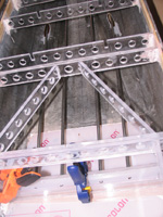 |
Once the four shaft exits points were cut in and shaped, I fabricated two locator jigs from some spare 1/4-inch polycarbonate. I used the patterns I
created in Solidworks to locate the shaft holes at the selected location. I used the aft face of Station 28 (stations are located every 21.5-feet on the real ship and
are not to be confused with frames) for the forward jig, and a point on the base place and eight inches forward of the extreme aft end of the hull for the after part.
This is the forward jig. |
| |
|
|
|
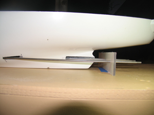 |
Here's the after jig in position under the hull. Note the shafts are sitting about 1/4" too low - I made a measurement error and cut the bottom of the
jig too short - easily corrected, but not tonight :). |
 |
Finally, here's a view of the shaft mock-up from the inside. You can see the lateral offset of the outboard shafts to good effect in this photo. |
| |
|
|
|
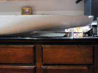 |
The flattest surface I have at home is the kitchen counters. So while my wife was out I set the hull up with the shaft jigs and snapped this photo.
I think this is getting pretty close to perfect. |
|
|
| |
|
|
|