Main Drive Installation
13MAR16 - Conceptually, I define the "main drive" as the following subsystems:
- main propulsion motors and their mounting system
- main and auxilliary power supplies
- main power control circuitry
- main motor speed controls
- steering controls, and
- radio components to support the above.
It took a while, but I was finally able to obtain the recommended motors for this project. Once I had them in hand, I took detailed measurements and modeled the
motors in Solidworks. I was then able to evaluate different mounting schemes within the hull.
Motor Installation Challenges
- Since the outboard shafts are not parallel to the centerline (per the prototype,
the distance between the outboard shafts and the centerline decreases moving forward), there is reduced spacing between the motors as compared to a traditional install.
- Given the restricted access once the maindeck is installed, I wanted a modular system which would allow for the removal of all four motors using minimal tools
- I wanted mounts which would securely and accurately hold the motors without impeding air cooling of the motor shells
- The end result had to provide a neat, tidy installation.
Power Supply and Control Circuitry Requirements
- The position of the batteries must not be restricted by any components: therefore nothing can be mounted to the base plate. This will permit maximum adjustability
of the batteries (within their compartments) when trimming the hull
- I wanted a single on/off control point for the entire power system. Given the electrical current requirements of the main propulsion motors, this would necessitate
the use of relays. For simplicity I used traditional electro-mechanical components for this function: I *might* change them over to solid state components at some future
time.
- Based on discussion with folks who have traveled this path before me, I settled on a power package comprising two large 12V batteries, and one smaller 6V battery for
auxilliary power.
- All subsystems must be removable with minimal tools: electrical elements must be easily disengaged via connectors.
- The end result must yield a neat, tidy installation.
My solution to these requirements is as shown in the diagrams and photos below.
Use the (vertical) scrollbar at right as needed. Clicking on any thumbnail will take you to a larger version of the photo.
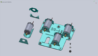 |
This is a rendering of the motor mount system (which I call the MPU or Main Propulsion Unit :) ). The system comprises
the base plate to which each motor is attached via front and rear mounts, a cradle, and a rear retainer. |
 |
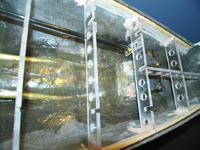
The MPU attaches to the hull via a series of socket-head shoulder bolts. These bolts screw into mating nuts embedded in
the hull. After maindeck installation, the aft-most bolts can be accessed via a long allen driver thru small holes in the deck. Each mount point is equipped
with a rubber insulating grommet. |
| |
|
|
|
 |
When needed, the MPU may be removed from the hull as a single unit by siliding it forward through the frame at Station 25,
and then lifting it up and out of the hull (obviously, the main batteries must be removed prior to this operation). |
 |
This is a view of the magnetic rudder mounting system. The grey ABS component will be permanently bolted and glued to the
adjoining beam. |
| |
|
|
|
 |
I used a Golden-Rod pushrod for the rudder, medium flexibility and large (4-40 hardware) size. The end is retained in a slot to
allow for side-to-side motion of the pushrod as it follows the rudder bellcrank. |
|
|
| |
|
|
|
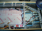 |
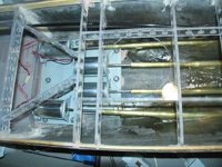
Moving on to the rest of the installation, I arrived at the following layout: on the port side, moving forward from Station 25:
2x ESCs, the 12Va and 12Vb relays, and 3x terminal blocks are mounted beneath the main deck such that they do not encroach the main battery compartment. The rudder servo
is mounted on the starboard side just forward of Station 25. |
 |
Back on the port side, the three terminal blocks sit beneath the master On/Off switch. This switch is a single pole, double throw
configuration, which allows me to select which of the main batteries supply current to the three relays. The small-gauge wire harness taps 6V current off the appropriate
terminal block and feeds it to the radio receiver. |
| |
|
|
|
 |
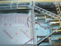
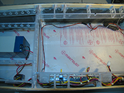
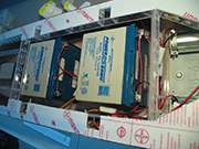
Moving forward past the main battery compartment is the 6V auxilliary battery and its relay. The battery is not attached to the hull yet pending
initial trim activities. |
 |
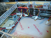
Low-angle view of the terminal blocks and main power switch (red circle - I just noticed the switch is crooked :( ). Eventually I'll tie multiple nodes of the blocks together
for Ground, +12Va, +12Vb, and +6V. The two loose tamiya connectors attach to the main battery harnesses. |
| |
|
|
|
 |
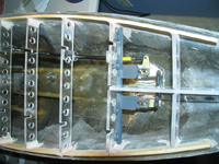
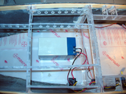
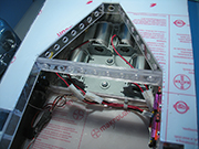
This view shows the two electronic speed controls along with the two 12V relays. The relays mount via a single bolt to a lexan standoff.
The ESCs each mount to a custom plate via a single wire tie. The plate bolts to the hull structure. The ESC outputs are split into two signals, which terminate in a Tamiya
connector, the other side of which connects to a motor.
I did mount the ESC power switches so that they are accessible: however since I'm powering the receiver from an unrelated source, these switches will always be "off." |
 |
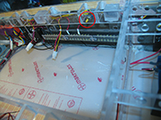
The aft maindeck is in place in this shot, giving an idea of access. I rewired the motors, upgrading from 24- to 18-gauge wire.
Motors with white heatshrink are wired in reverse of those with black, to achieve the desired counter-rotation of the shafts. The radio receiver and its associated
wiring has not yet been installed. |
| |
|
|
|
 |
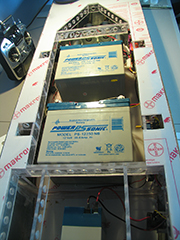
Here, the maindeck is in place both fore and aft, and (obviously) the main batteries are installed. Like the 6V battery,
these are not yet attached, pending trim work. The yellow toggle of the main power switch is visible in the lower left corner of the image. I plan to install
a magnetic reed switch in parallel with this toggle to enable on/off control without removing the superstructure. |
 |
... and an overview of the installation looking aft. |
| |
|
|
|
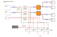 |
Finally, here is the basic schematic for this equipment in case anyone is interested. No magic, certainly nothing proprietary. If you have questions/suggestions,
send them to rlacm at cox dot net. |
|
|
| |
|
|
|
|